Non ASME standard flange design. Welcome to this interactive flange bolting calculator from HYTORCThe program computes recommended torque values bolting patterns tool selection and pump pressure settings for standard ASME B165 and API 6A flanges under normal assembly conditions.
2
Number size and type of bolt The number and size of the bolts is given when using.

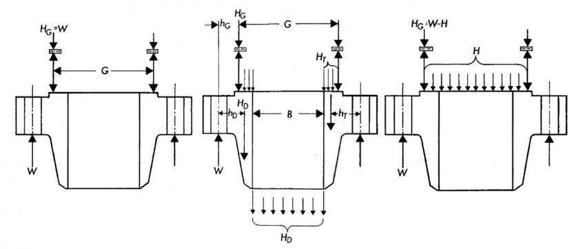
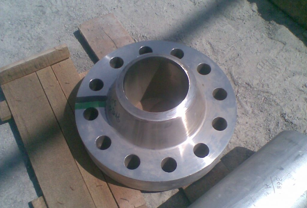
. These flanges have special characteristics requiring a specific design process to fit the working. Non Standard Flange Design Calculation. D4 - K0-D d3- K0 - D SLIP-ONPLATE TTT WELDING NECK BLIND.
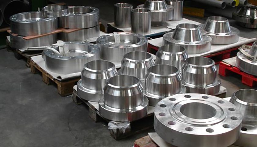
For approximately the last three years ULMA Piping has been learning and incorporating new methods and technologies for the design of non-standard flanges. Smaller bolt diameters will indeed generally yield a smaller more compact flange it is generally preferred. The standard thickness of the raised face is 006in 15mm for all flange ratings up to and including 300lb and 025in 635mm for all other flange ratings.
Allowable stress at design temp. Inspection Tests Marking and Records. Modulus of elasticity at atmospheric temp.
Materials of Construction and Allowable Stress Values 3. This may require several changes in the body of the specifications. Click the register link above to proceed.
For Non-Standard Flanges. For approximately the last three years ULMA Piping has been learning and incorporating new methods and technologies for the design of non-standard flanges. Their design section to direct the designer to this new standard instead of the 2004 Code.
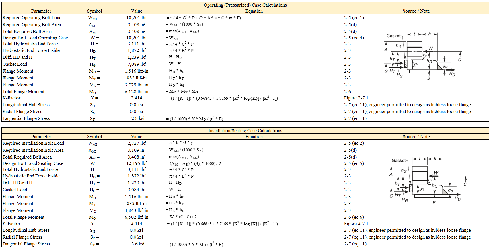
Dimensions Sizes and Specification of DIN Flange DIN Standard Flanges Pressure Rating from PN6 to PN 40 Slip On Flanges Blind Flanges Welding Neck Flanges DIN 254 SLI4 -P ON FLANGE S DIN 252 BLIN7 FLANGED S DIN 263 WELDIN4 NECG FLANGEK S SEE DIN 2559 d2 d2 I. We have to proceed a design calculations as per ASME code Section VIII Division 1-Mandatory Appendix 2 Rules for Bolted Flange Connections with Ring Type Gaskets about 10 pages of detailed calculations per flange integral loose and optional type and blind flange shall be carried out in accordance with ASME UG-346 6 pages. General Materials and Design 1.
For both standard and non-standard flanges. SnTMan Mechanical 4 Apr 18 1419. It was probably introduced because the table 2-51 gasket factors are too high.
2 shows flow chart for design Automation of non standard flange. 32 Bolt characteristics This area displays information con - cerning the bolts of the flange. For example based on visual leak evidence or.
The1004 ASME Code Section VIII Division 2 can be removed as a referenced standard and Standard 6X added. Modulus of elasticity at design temp. Most true flange design programs will start with a small bolt typically 34 and determine whether a sufficient.
Welding Qualifications Section III. Types of spacer in industry. Manufacture and Workmanship 7.
You may have to register before you can post. If this is your first visit be sure to check out the FAQ by clicking the link above. In many cases the chemical formula is shown automatically.
The Flange design and calculation of ULMA Piping certified for by the API and ISO. Flange Calculations for Non-Standard Flanges 5. The Flange design and calculation of ULMA Piping certified for by the API and ISO.
Removes any possible correlation between ASME flange calculation methods and flange manufacturers provided m and y values. Note not a better flange but a cheaper one. 2 part 416 13 calculations.
The seating and operating loads are design rules and should not be expected to predict actual flange stresses. Fabrication and Welding 6. Foreword Section I.
Further use of Dialog control language boxes enriches the program and provides user friendly environment. Non standard ASME Flange Design Calculations Excel sheet for Pressure Vessel. Since 17D refers to 6A for design requirements no change is needed.
To start viewing messages select the forum that you want to visit from the selection below. The length of the flange L. The raised face is not included in Flanges strength calculations.
The non standard flange design automation program is written in Auto LISP language compatible with AutoCAD Drawing package. Moreover ULMA can also supply special and non-standard flanges design calculation manufacturing and testing and critical joints SUBSEA that guarantee the integrity utility and durability of the flange joint flange seal spacer seal flange bolts nuts. Pressure Relieving Devices Section II.
Internal design pressure P. Root diameter d b. The concentration of the me - dium has also to be entered.
Non standard flange design calculation In case you are a lover of nail art but are certainly not accustomed to the various coats of acrylic then such a design could possibly just function nicely for you. Torque calculations are based on the simplified formula explained in the current version of. Allowable stress at atmospheric temp.
Waters method is established on the basis of online elastic plate and shell theory of non-standard flange design calculation method whether it is internal pressure flange or external pressure flange in addition to the flange moment calculation formula is different according to the flange ring and cylinder or including tapered neck connected to the degree. As th e calculation meods ar limited so standards us real test requirement to ensure compliance for non-standard components. That type of flange connection cannot be assessed by using ASME VIII Div.
These flanges have special characteristics requiring a specific design process to fit the working conditions.
Non Standard Flanges Asme Viii Arveng Training Engineering

How To Calculate Blind Flange Thickness Www Steeljrv Com
Non Standard Flanges Asme Viii Arveng Training Engineering
Asme Flange Design Calculation

Non Standard Flange Design And Bolt Tightening Basis Video1 Youtube
Non Standard Flange Calculations Video 2 عربي Youtube

11 How To Design Nonstandard Flanges On Standard Nozzles Autopipe Wiki Autopipe Bentley Communities
Flange Thickness Calculation Sk
0 comments
Post a Comment